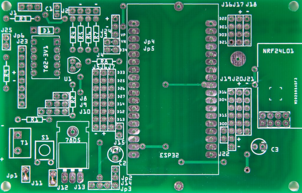
The « ESP32 DEVKIT V1 DOIT Expansion shield » board is a multifunctional board for mounting applications with the ESP 32 DEVKIT V1 DOIT. The card is not dedicated exclusively to one function, it is the user who will determine the parts and the assembly according to his specific needs.

The first step is to decide the supply voltage at the input of the board. Several components, sensors use 5 volts, so it is a good choice to supply the card with 5 volts, which will be redistributed by it.

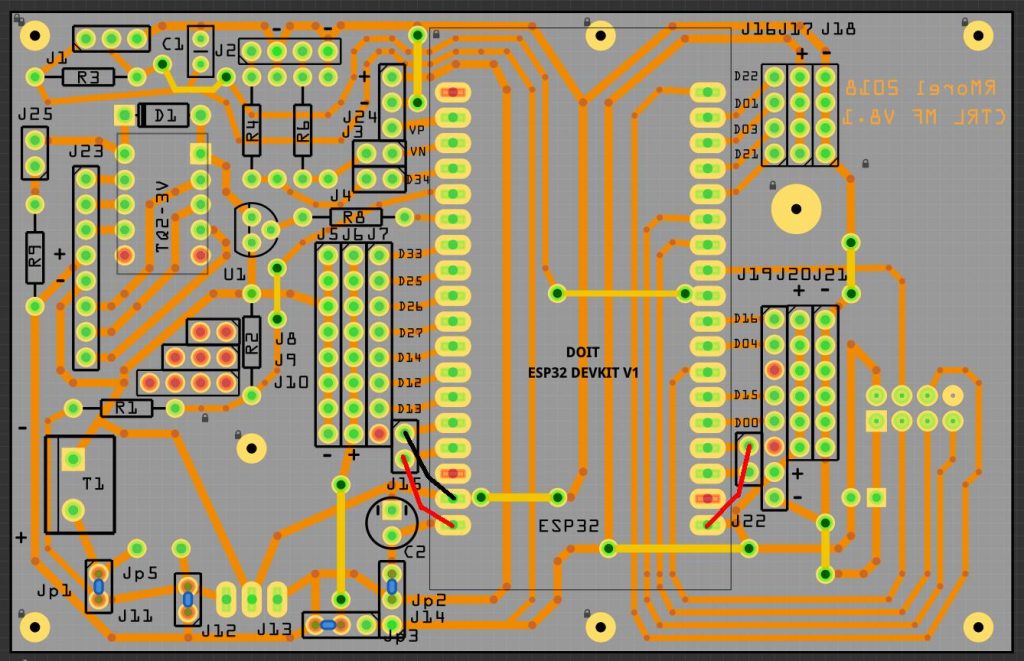
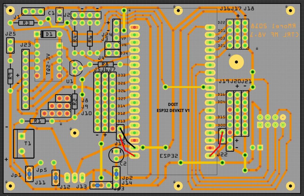
The 5 volt power supply is connected to input T1. Four jumpers, shown in blue, are added to distribute the 5 volts to the ESP32 and the + line J6.
A terminal block with screws is soldered to position T1, as well as a 10 µf 35 V capacitor to position C2

In the board above 3 jumpers ( one black, two red ) are soldered in anticipation of the use of a 30-pin ESP32. For the 36-pin ESP32, of course, three jumpers are not required.

Personally, I don’t solder the ESP32 directly to the board, I install « SIL Socket Row Strip PCB » female connectors to receive the ESP32.

For the external links, I install « SIL Socket Row Strip PCB » male connectors.
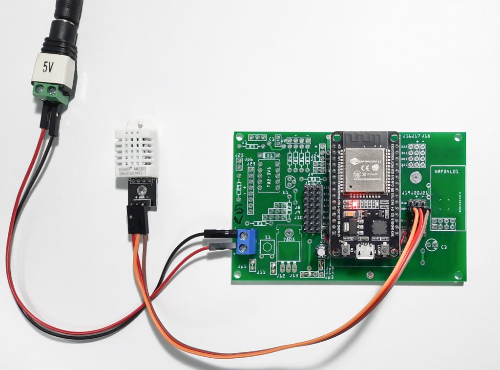
Example of assembly with a DHT22 temperature and humidity sensor
